Constraint editor
When adding or removing operations to a route the operations will be added with a default constraint from the previous operation end to the new operation start. The constraint editor allows further editing of the network:
Notice that it is also possible to edit the network manually by editing the Depends on column.
The following provides an overview of how to achieve different results with the constraint editor.
| Starting point | Intermediate step | End result | How-to |
 |
 |
 |
1. Remove the constraint between cutting and welding 2. Add new constraint between cutting and painting |
 |
 |
 |
1. Remove constraint between welding and painting 2. Add new constraint between cutting and painting |
 |
 |
 |
1. Add new constraint between cutting and painting |
Constraint types
The properties of the different constraints vary depending on the object types of the selected constraint source and destination. The following table lists how the editor supports and visualizes the different constraint types.
| Constraint type | Source type | Destination type | Constraint line color | Supported actions | Comments |
| Route constraint | Operation | Operation | Black | Add Remove Edit |
Used from the edit route window and from the edit operation dependencies tab. New constraints of this type can be added between two operations. |
| Route network constraint | Route | Route | Black | Add Remove Edit |
Used from the edit route networks window |
| Sub-order link | Production order | Production order | Blue | Edit | Used from the edit operation dependencies tab. Use the right click menu of the Gantt chart to add/remove sub-order links between orders. |
| Material dependency (pegging links) | Operation or counting | Operation | Green | Edit | Used from the edit operation dependencies tab. To add material dependencies between operations: * Use the right click menu of the Gantt chart to manually add material dependencies * Use the Pegging macro to automatically add material dependencies. Use the edit operation materials tab to remove a material dependency. |
General features of the constraint editor
This chapter lists the general editing functionality of the constraint editor.
Maneuvering within the graphics view

To move all objects to a different position, press and hold the left click button of the mouse anywhere in the white background and move the mouse.
To move a single object left click with the mouse anywhere on the object and drag it with the mouse.


Adding a new constraint line
- Press and hold down the Ctrl key while dragging the mouse from the source object (e.g. operation or route) to anywhere on the destination object. A dashed line will be drawn while dragging.
- While the mouse arrow is on top of the destination object, and still with the Ctrl key pressed, let go of the left mouse key
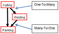
Note that it is possible to add constraint lines with both one to many and many to one relations ships between source and destination.
Selecting a constraint line to edit
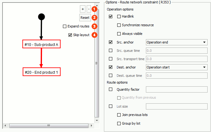
To select a constraint left click anywhere on the constraint line with the mouse. Once selected the constraint line color turns red and the right side property editor becomes enabled. The properties depends on the type of constraint selected, but as an example it is possible to specify anchor in/out for both source and destination etc. Any value provided will overwrite the default value specified on the operation, route or project.
Removing an existing constraint line
Select the constraint line by left clicking anywhere on the constraint line with the mouse. Once selected press the Delete key on the keyboard. Removing a constraint cannot be undone!
Constraint options
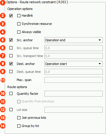
The constraint options are listed in the right panel of the constraint editor, and are grouped in options applicable for constraints between operations and between routes (routing options are only visible when editing Route Networks). Selecting a checkbox in the left column of checkboxes, means that the corresponding option on the operation or route is overridden.
 |
Route constraint ID | Identifier (ID) of the constraint. Used for troubleshooting. |
 |
Hardlink | The destination object will follow immediately after the source object. Locks the source and destination objects together so they are moved as one entity. If you are looking for a “hardlink option” with the ability to flex the time between two operations, look at the Max span option. |
 |
Synchronize resource | Source and destination operations will be synchronized to use the same resource. If a operation is then moved to another resource – the other will be moved simultaneously to the same resource. Scheduling note: During scheduling some limitations are in place. The first operation in a synchronize resource group finds the “best” resource and the remaining operations with “synchronize resource” are bound to stick to this resource (even though better resource combinations might be available!) |
 |
Always visible | The constraint will always be visible in the gantt chart, regardless of whether or not the source or destination is selected. |
 |
Src. anchor | Source anchor – The anchor going out of the source object. |
 |
Src. queue time | Source queue time – Outgoing queue time from the source object. |
 |
Src. transport time | Source transport time – Transport time from the source object. |
 |
Dest. anchor | Destination anchor – The anchor going into the destination object. |
 |
Dest. queue time | Destination queue time – Ingoing queue time to the destination object. |
 |
Max span | Available from v7.4: A maximum no. of hours allowed between two operations during scheduling. If the max span limitation as an example is manually broken by Gantt chart drag/drop of an operation, the constraint line will become red. Also, this will cause the operation to turn red in color mode “Broken constraints”. The current implementation does not work with Max span settings for both incoming and outgoing constraints to/from the same operation. The scheduling will warn about this in case this is modelled. |
 |
Quantity factor | Will be multiplied by quantity specified on the project/previous level, to calculate the needed output quantity of the next level. |
 |
Quantity from previous | The output quantity from previous level (route) is multiplied by the quantity factor. |
 |
Lot size | If the quantity of the project is 10 and lot size is 5, 2 production orders will be created with quantity of 5 each. |
 |
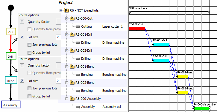
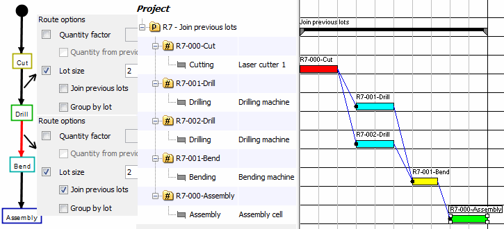
Join previous lots | “Join previous lots” is not selected in the below example. (Quantity is 4 and lot size 2) |
Same as above, but this time “Join previous lots” IS selected. Lots are merged into one production order.
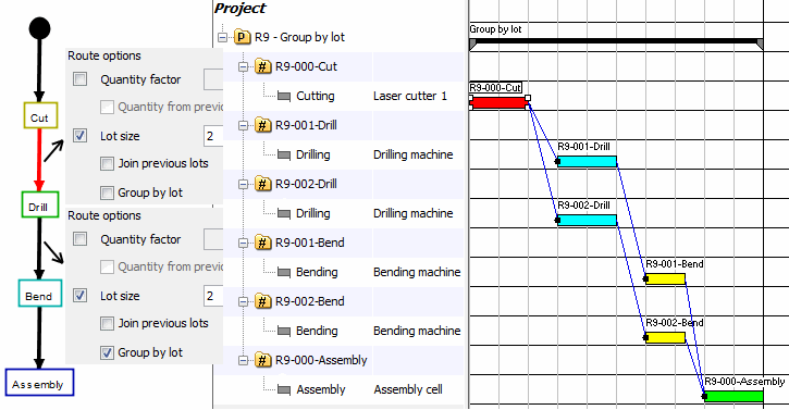
Same as above, but this time “Group by lot” IS selected.



Post your comment on this topic.