
The route network features allow a product to be modeled as a multi level part list. It can be thought of as a bill of material (BOM), but instead of materials it is the route that is the building block.
A route network is used as template for a project, i.e. the project is created whenever a product (as an example a machine) is planned to be produced. At the creation time of the project, the route network will be unfolded, facilitating the automatic generation of production orders on different levels. Each level of production orders are linked to other levels using sub-order links.
The route network feature is especially relevant for machine builders or similar, with manufacturing of multiple intermediate machine parts all being assembled into the final customer end product.
Introduction
The concepts and normal work flow of routing networks are best explained with an example. The example being explained is for a bicycle manufacturing shop.
This example is also available as a ROB-EX planning file located in the file \data\bike manufacturing.xml ( ). This file can be opened in a ROB-EX client using the “File->Open” menu option, while not being logged into a ROB-EX Multiuser Server.
This first picture shown above, is a diagram of the intermediate components going into building the final bicycle and the quantities needed for each of the intermediates.
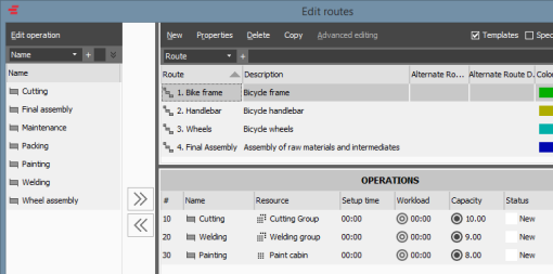
The above picture shows how master routes for the different intermediate products are created as normal master routes from the “Edit->Routes” window.
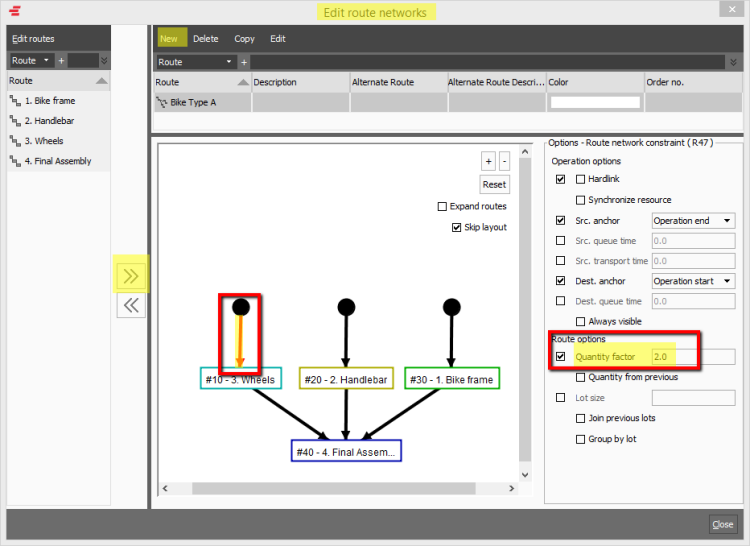
The next step is shown in the picture above. The “Edit route networks” window is opened from the “Edit->Route networks” menu. A new Route Network is created by clicking the “New” button, and using the right arrow key and the functionality of the constraint editor, the structure of the end product is modeled. Notice the constraint options for the constraint line highlighted in yellow, showing how to model that a quantity of 2 wheels are needed for every bicycle produced.
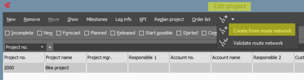
Once the route network master data is in place, the final step is to create a project as shown in the picture above:
- A new project is created clicking the “New” button in the toolbar
- The quantity to produce is entered (in this example 3 bicycles)
- The “Create from route network” action is triggered from the toolbar which will traverse the created route network, creating the necessary production orders for the different levels. The “Validate route network” action can also be chosen to explode the route network, allowing the user to validate and confirm the generated structure before committing to actually create the production orders.
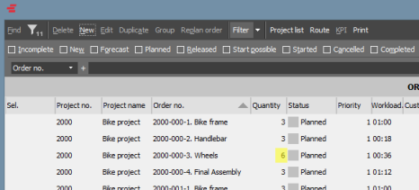
The result of the new project as visualized in the order list shown on the above picture. Notice the high lighted “Quantity” column: i.e. because of the “Quantity factor” of 2 specified on the “Wheels” constraint line (see above), the amount on the generated “Wheels” production order is twice that of other orders in in the project.
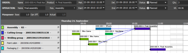
The result of the new project as visualized in the Gantt chart is shown on the picture above, notice the automatically generated blue sub-order lines connecting the intermediate production orders with the final assembly order.
Post your comment on this topic.